Projects

Uncategorized

PCB Fabrication – Aluminum vs Copper base for 4-Layer MCPCBs

1. Introduction

Printed Circuit Boards (PCBs) are the backbone of modern electronics, providing the physical platform for mounting and interconnecting various electronic components. For high power components, efficient heat management is crucial, and this is where Metal Core Printed Circuit Boards (MCPCBs) come into play. In this blog post, we’ll explore the fabrication of 4-layer MCPCBs using aluminum and copper substrates, focusing on their effectiveness in rejecting heat.

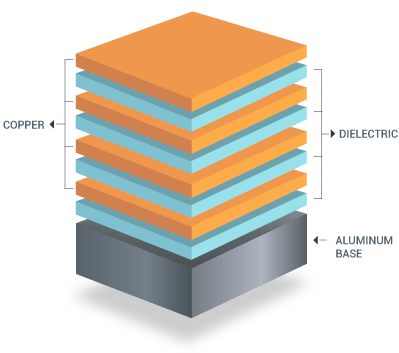
2. Understanding Metal Core PCBs (MCPCBs)

MCPCBs, also known as thermal PCBs or metal-backed PCBs, incorporate a metal core to enhance heat dissipation. This core acts as a thermal conductor, drawing heat away from critical components to prevent overheating. Aluminum and copper are the most commonly used metals in MCPCBs due to their excellent thermal properties.

3. Aluminum MCPCBs for 4-Layer Boards

Properties of Aluminum: Aluminum is known for its excellent thermal conductivity and lightweight nature. These properties make it a popular choice for MCPCBs in applications where heat dissipation is critical.

Advantages of Using Aluminum MCPCBs:

  • Thermal Conductivity: Aluminum MCPCBs efficiently dissipate heat away from high power components, reducing the risk of overheating.
  • Cost-Effectiveness: Aluminum is generally more affordable than copper, making it a cost-effective solution for many applications.
  • Lightweight: Aluminum’s lightweight nature makes it ideal for applications where weight is a concern, such as in aerospace and portable devices.

Challenges:

  • Manufacturing Complexity: Fabricating multi-layer MCPCBs with aluminum can be challenging due to its thermal expansion properties.
  • Electrical Performance: Aluminum is not as conductive as copper, which can affect the overall electrical performance of the PCB.

4. Copper MCPCBs for 4-Layer Boards

Properties of Copper: Copper is renowned for its superior thermal and electrical conductivity. These characteristics make it an excellent choice for high power MCPCBs.

Advantages of Using Copper MCPCBs:

  • Superior Thermal Conductivity: Copper MCPCBs provide unmatched thermal performance, efficiently managing heat dissipation.
  • Electrical Performance: Copper’s high electrical conductivity ensures optimal performance of the PCB.
  • Durability: Copper substrates are highly durable and resistant to corrosion, enhancing the longevity of the PCB.

Challenges:

  • Cost: Copper is more expensive than aluminum, which can increase the overall cost of the MCPCB.
  • Weight: Copper is heavier than aluminum, which may not be suitable for weight-sensitive applications.

5. Comparative Analysis: Aluminum vs Copper MCPCBs

Thermal Conductivity Comparison: Copper has a higher thermal conductivity than aluminum, making it more effective in heat dissipation. However, aluminum’s thermal performance is still significantly better than that of traditional FR4 substrates.

Electrical Performance Comparison: Copper’s superior electrical conductivity makes it the preferred choice for high-frequency and high-power applications, where electrical performance is crucial.

Cost and Manufacturing Complexity: Aluminum is more cost-effective and easier to work with compared to copper, which requires more complex manufacturing processes and higher material costs.

Weight and Durability: While aluminum is lighter, copper’s durability and corrosion resistance provide a longer-lasting solution for many high-stress environments.

6. Case Study: Heat Rejection in High Power Components

Consider a scenario where a high-power LED driver is used. The heat generated needs to be efficiently managed to ensure longevity and performance. In such cases, a copper MCPCB might be preferred due to its superior thermal and electrical performance, despite the higher cost. On the other hand, for applications where cost and weight are more critical, aluminum MCPCBs provide a balanced solution with adequate thermal management.

Real-World Applications:

  • LED Lighting: Both aluminum and copper MCPCBs are used, with aluminum being more common due to its cost-effectiveness.
  • Power Electronics: Copper MCPCBs are often used in high-end power supplies and converters.
  • Automotive Industry: Both materials are used, depending on the specific thermal and weight requirements.

7. Conclusion

Choosing the right substrate material for a 4-layer MCPCB is crucial for efficient heat rejection, especially in high power applications. While copper MCPCBs offer superior thermal and electrical performance, aluminum MCPCBs provide a cost-effective and lightweight alternative. The decision ultimately depends on the specific requirements of the application, balancing factors such as thermal management, cost, weight, and durability. As technology advances, the development of new materials may offer even better solutions for managing heat in high power MCPCBs.

By understanding the strengths and limitations of aluminum and copper MCPCBs, engineers can make informed decisions to enhance the performance and reliability of their PCBs.

Uncategorized

INFOGRAPHIC: PCB Stackups

As part of my formal PCB layout courses at Indiana Tech in Fort Wayne, I recently completed an assignment to create an infographic detailing the PCB stack-ups with guidelines for design. This exercise highlighted the importance of carefully choosing what goes on each layer of a PCB to optimize signal integrity, reduce electromagnetic interference (EMI), and ensure efficient power distribution.

Uncategorized

3D Printing Sample Material Swatches and Storage Box with Labels

3D printing is an incredibly useful tool for creating a wide variety of objects, from prototypes to finished products. One important aspect of 3D printing is the material you use to print your object, as different materials have different properties and can produce significantly different results.

One way to ensure that you are using the right material for your project is to print sample swatches before you begin your main print. Sample swatches are small test prints that allow you to see what a particular material will look and feel like, as well as how it will behave during the printing process.

There are a few key reasons why printing sample swatches is important:

  1. Material properties: Different materials have different properties, such as strength, flexibility, and durability. Printing sample swatches allows you to see firsthand how these properties will affect your final print.
  2. Printing quality: Some materials may require different print settings in order to achieve the best results. Printing sample swatches allows you to fine-tune your printer’s settings to ensure that your final print is of the highest quality.
  3. Cost savings: Printing sample swatches can save you money in the long run by allowing you to test different materials before committing to a full print. If you find that a particular material doesn’t work for your project, you can avoid wasting time and resources by switching to a different material before you begin your main print.

Overall, printing sample swatches is a valuable tool for anyone using a 3D printer. It allows you to make informed decisions about which material to use and how to set up your printer, which can ultimately lead to more successful and cost-effective prints.

For my personal printing I found the STL file for the swatches at the following location:

https://www.printables.com/model/111326-filament-swatch-library/files

While for the box, I did not like the lid on the option above so someone had already made a compatible bottom only here:

https://www.printables.com/model/343165-open-filament-sample-box

Then to give the swatches a nice label I used QR Code Monkey to Generate QR Codes of the links that I used to purchase the material for easy ‘re-filling’ of the material when supplies run low.

https://www.qrcode-monkey.com/

To print the labels I used a Brother QL-710W label maker with the P-touch Editor to create the labels that stick onto the swatches. The QR Codes created in QR Code Monkey were simply copied and pasted directly into the label.

Uncategorized

Upgrading Monoprice Voxel 3D Printer to a FlashForge Adventurer 3!

The Monoprice Voxel is an excellent small form factor fully enclosed 3D Printer. There are a few pitfalls however, the first of these is that the Firmware and Software have not been updated since 2019 by Monoprice. The good news is you can upgrade both of these by flashing new firmware from the FlashForge Adventurer 3!

FlashForge did a white label version of their Adventurer 3 printer for Monoprice, and they still sell it. They also are constantly making improvements to their “FlashPrint” software and are upgrading their Firmware.

https://www.flashforge.com/product-detail/flashforge-adventurer-3-3d-printer

Upgrading the firmware in the Voxel is a pretty easy task and made easier by the instructions that u/Jimmy0x52 on Reddit posted a couple of years ago. These instructions need a few very “small” updates that I have created below.

https://www.reddit.com/r/FlashForge/comments/jchhmp/voxel_users_heres_how_to_upgraded_to_latest/

  1. Visit https://drive.google.com/drive/folders/1AX-GupCoJoM6Qhpwi5jL2lG6fnh4O4Dk and download one version newer than your Voxel’s firmware.
  2. Unzip into a new folder
  3. Format a USB stick. (Mac=MSDOS FAT, Windows=FAT32)
  4. In the firmware folder open the file flashforge_init.sh in a text editor (note: Use NotePad++, Sublime Text).
  5. Delete lines 22-31 (See below for the lines to delete)
  6. Save the updated file
  7. Copy all of the files from the firmware folder to your formatted USB Drive
  8. Power down your Voxel, Insert the drive into the front USB port, Turn the Voxel on. You should see the update screen. In a few seconds it will make three chimes. You can remove the USB and restart the printer.
  9. Finally if the Voxel is connected to the internet the firmware will automatically begin updating multiple times until the latest firmware is loaded.
  10. Your Voxel printer is now a FlashForge Adventurer 3!!!

Lines of code to comment out that allow for the Voxel firmware to be overwritten by Adventurer 3 firmware:

#screwflag为丝杆标志文件,存在说明在工厂里,可任意升级
if [ ! -f $WORKDIR/screwflag ]; then 
	#第1、2个参数为空,说明没有传递参数,为老版本固件,可升级
	if [ "$1" != "" ] && [ "$2" != "" ];then
		if [ "$1" != "${MACHINE}" ] || [ "$2" != "${PID}" ];then
			echo "Firmware does not match machine type."
			exit 1
		fi
	fi
fi

Now that your printer now is a FlashForge Adventerure 3 you can use the latest FlashPrint software found here:

https://www.flashforge.com/product-detail/FlashPrint-slicer-for-flashforge-fdm-3d-printers

Uncategorized

Getting Started with SDR and HackRF One (Windows Based)

HackRF One From Great Scott Gadgets

Getting started with Software Defined Radio (SDR) has never been easier thanks to GNU Radio and the various SDRs available. I have decided to start learning about SDR using the ‘HackRF One’ from Great Scott Gadgets (link).

I am following along with the Great Scott Gadgets website tutorials put on by
Michael Ossmann. I have just completed the first set of code and instruction video. My particular notes are below on getting started with Windows, GNU Radio and my source code.

After the installation steps in the list above, it is as easy as opening up GNU Radio Companion and following the steps laid out by Michael to create your first FM Radio.

GNU Radio Companion
FM Tuner with Band Visualization GUI.

The only major hiccup that I found was that in the demonstration was that his sample rate was 20M s/sec, this was much too fast for my PC and had issues keeping up. Once I turned down the sampling rate down to 10M s/sec the tuner was crystal clear and worked great.

FM Tuner with Spectrum Visualization and Variable Tuning

More to come as I complete future lessons and eventually start listening to the ham radio bands and use this to modify my low cost radar project.