I have been a subscriber to hackerboxes.com for quite some time, however, I typically just get their boxes every month, review the contents and set it aside for another ‘not so busy day.’
http://www.instructables.com/id/HackerBoxes-0020-Summer-Camp/
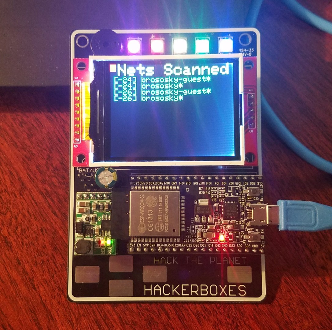
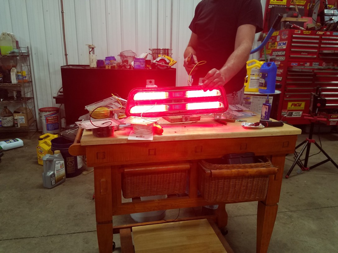
Today I decided to pull out an older box, the ‘Summer Camp’ Badge box. This box has you build an program an ESP32 connected to a TFT, 5 neopixels, cap touch buttons printed on the board, a lipo battery charger and a buzzer. The board builds in about 30 minutes, and takes about 30 more to setup the IDE and test all of the functions. A photo of my build running is below, it is scanning all of the SSIDs that it can see and displaying them to the TFT.
The notes from instructables do leave out a few key things that I will list below for anyone else working through this tutorial and having issues:
1.) You will need to get and install the following Arduino libraries from github (remember to restart the Arduino IDE after adding new libraries to the ./Arduino/libraries folder:
https://github.com/adafruit/Adafruit_ILI9341
https://github.com/adafruit/Adafruit_NeoPixel
https://github.com/adafruit/Adafruit-GFX-Library
2.) When you install the ESP32 tool suite from github, you will need to select the ‘ESP32 Dev Module’ as your board. The instructions are fairly straight forward, the biggest thing to remember to do after you clone the repository to your ./Arduino/hardware directory is to run the ‘get.exe’ command to install the ESP32 tools in the Arduino IDE.
https://github.com/espressif/arduino-esp32
Next Steps:
Next I will be adding the ability to do the following from a web interface:
1.) Change the text on the TFT
2.) Set the NeoPixels
3.) Play sounds on the Buzzer
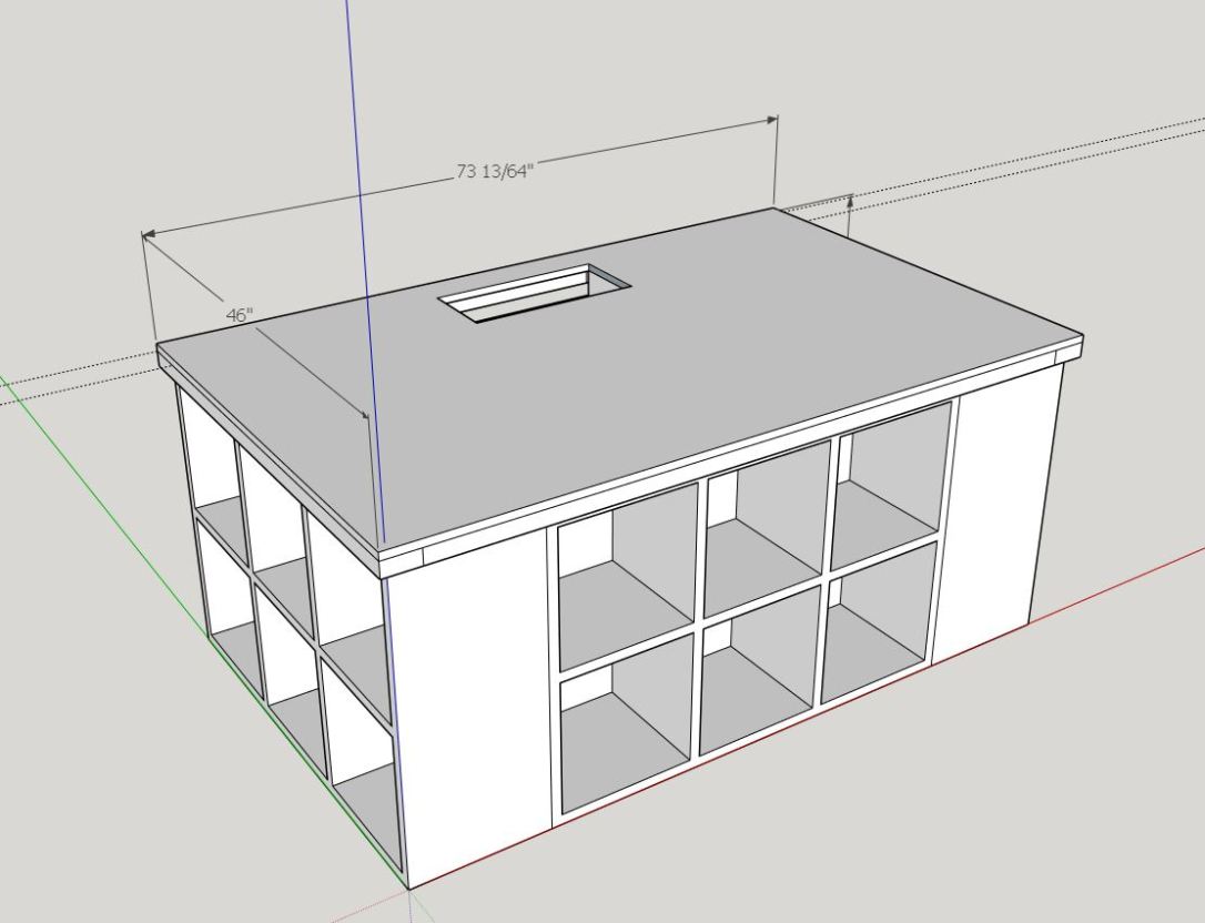
The ultimate goal will be to use an ESP32 module on my own board to control above and under cabinet neopixel strings that can be controlled via a webapp.
*More to come!


 I
I