

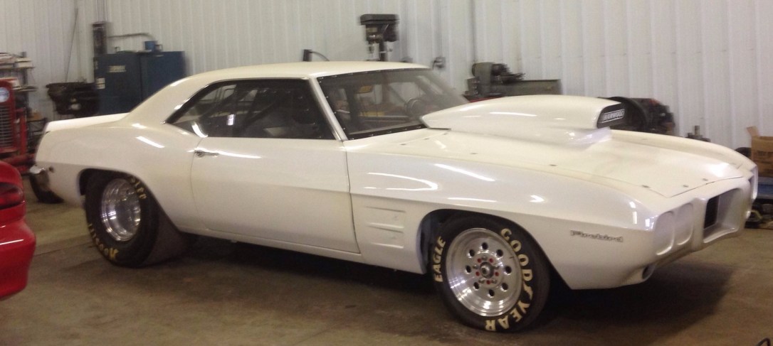
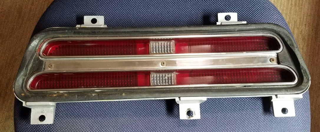
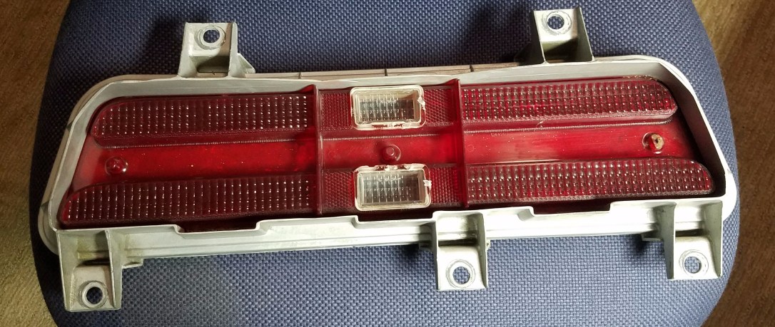
My brother built a 1969 ProStreet Firebird (shown in the photo above). He has asked that I create some LED taillights to make this street legal. Below are photos of the housing that he had modified when turning it into a track car (he cut off the metal housings). I have both housings in the shop, but they are symmetric and not really worth taking the space to show here.
So after researching some LEDs, working on a few designs and using a couple of online tools I came up with a prototype design. First, I started by selecting a red and white narrow beam, high intensity LED. I choose a CREE CP42B-RKS-CL0P0AA4 for the red led and a CREE CP41B-WGS-CK0P0154 for the white led. The specs of these LEDs are below:
Red CREE CP42B-RKS-CL0P0AA4:
Voltage – Forward (Vf) (Typ) 2.5V
Current – Test 70mA
Viewing Angle 120°
Mounting Type Through Hole
White CREE CP41B-WGS-CK0P0154:
Voltage – Forward (Vf) (Typ) 3.6V
Current – Test 30mA
Viewing Angle 90°
Mounting Type Through Hole
I sketched out the dimensions of the taillights and calculated the number of LEDs and placement of each of the LEDS using DraftSight (an AutoCAD clone):
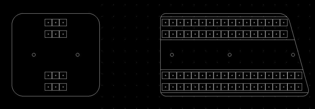
DraftSight screen capture to space the LEDs properly.
I found that we could save a PCB print if we simply flipped one side over since the housings are symmetric. To calculate / design the LED networks with resistors I used an online tool to give me a quick solution. The tool I used was http://led.linear1.org/led.wiz you can see the results of their design below:
 I
I
Screen capture of web based design tool.
I ended up using these values for the BRAKE function of the taillights. I then computed the 50% power version for the PARKING function of the taillights and used a 1N4001 Rectifier diode to allow for the dual brightness function.
I drew the schematics for the lights in MultiSim, you can see the RED section below… The WHITE section is very similar and can be downloaded on my GIT repository (there is a link at the end of this)…

Screen capture of the Red Section of the Taillights from MultiSIM.
If you would like a more clear (or actual print of this schematic, please feel free to contact me).
I did breadboard these just to make sure the brightness looked right and that everything worked okay. The breadboard worked great, as did the breadboard for the White reverse lights as well.
At this point I went and laid out both the RED board and the WHITE board, you can see the result below. To place each of the mounting holes and the LEDs I used the Import tool to bring in the DXF file.
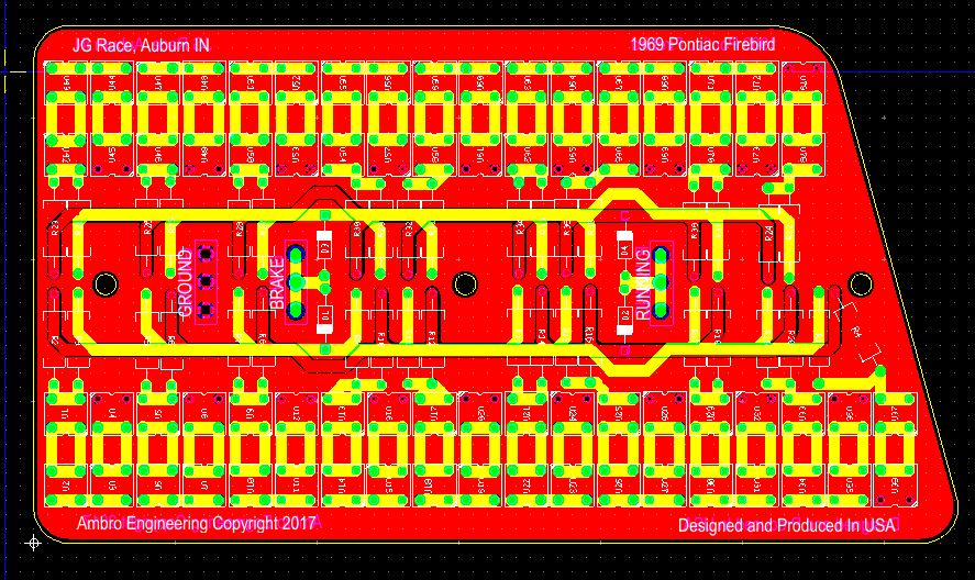
Red Portion of the Taillights
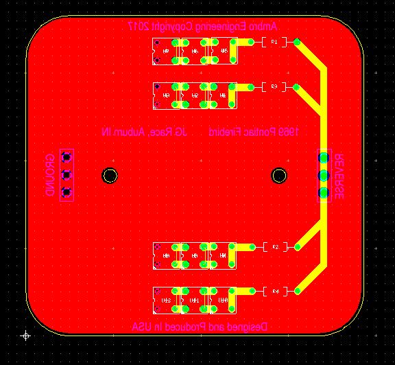
White Portion of the Taillights
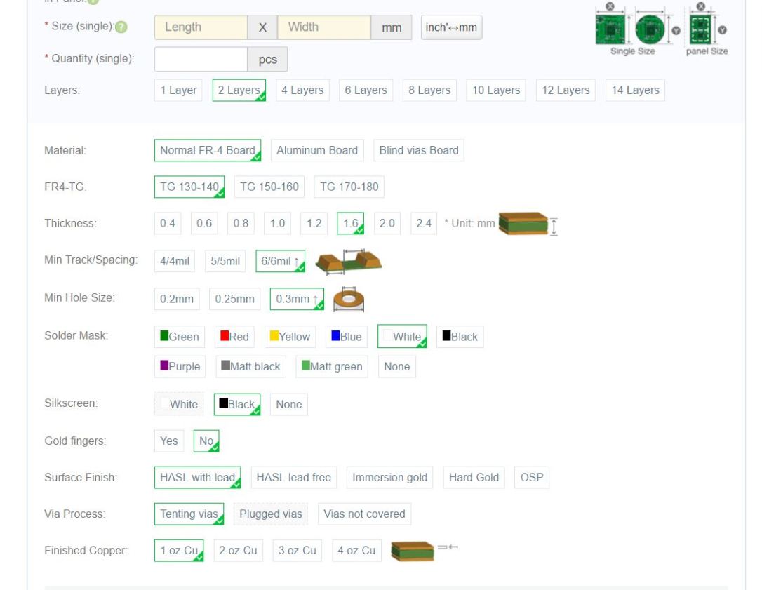
At this point, I checked and rechecked the layout, it came time to order all of the parts, which I did from both Mouser and DigiKey. I also ordered the boards from PCBWay.com. I spec’d the following:
Within a week I received the boards, and they turned out great. See the image below:

Unpopulated LEDs from PCBWay.com.
Once I got these boards in I assembled them, starting with the through hole resistors and then I moved on to the LEDs on each panel.
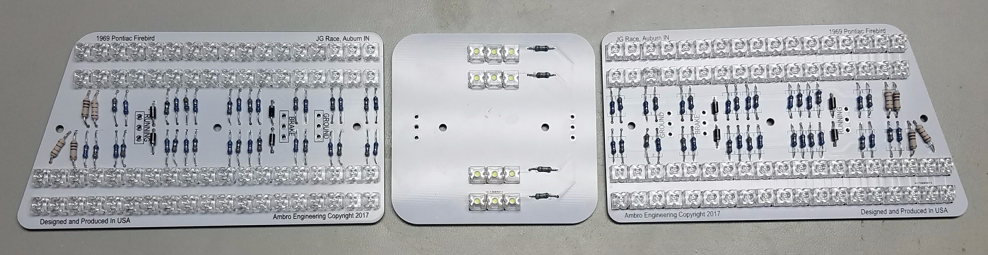
Assembled PCBs.
Below you can see the testing results:
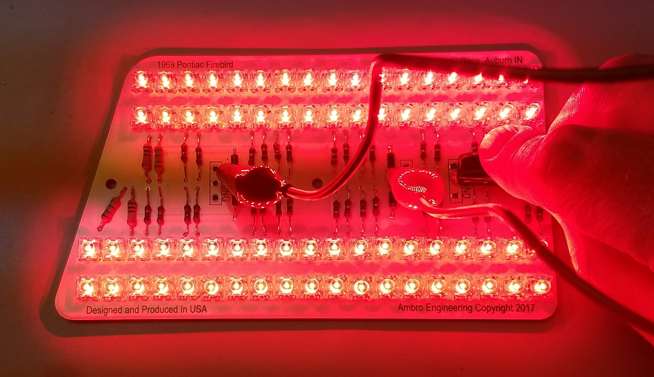
Testing the RED LED board section.
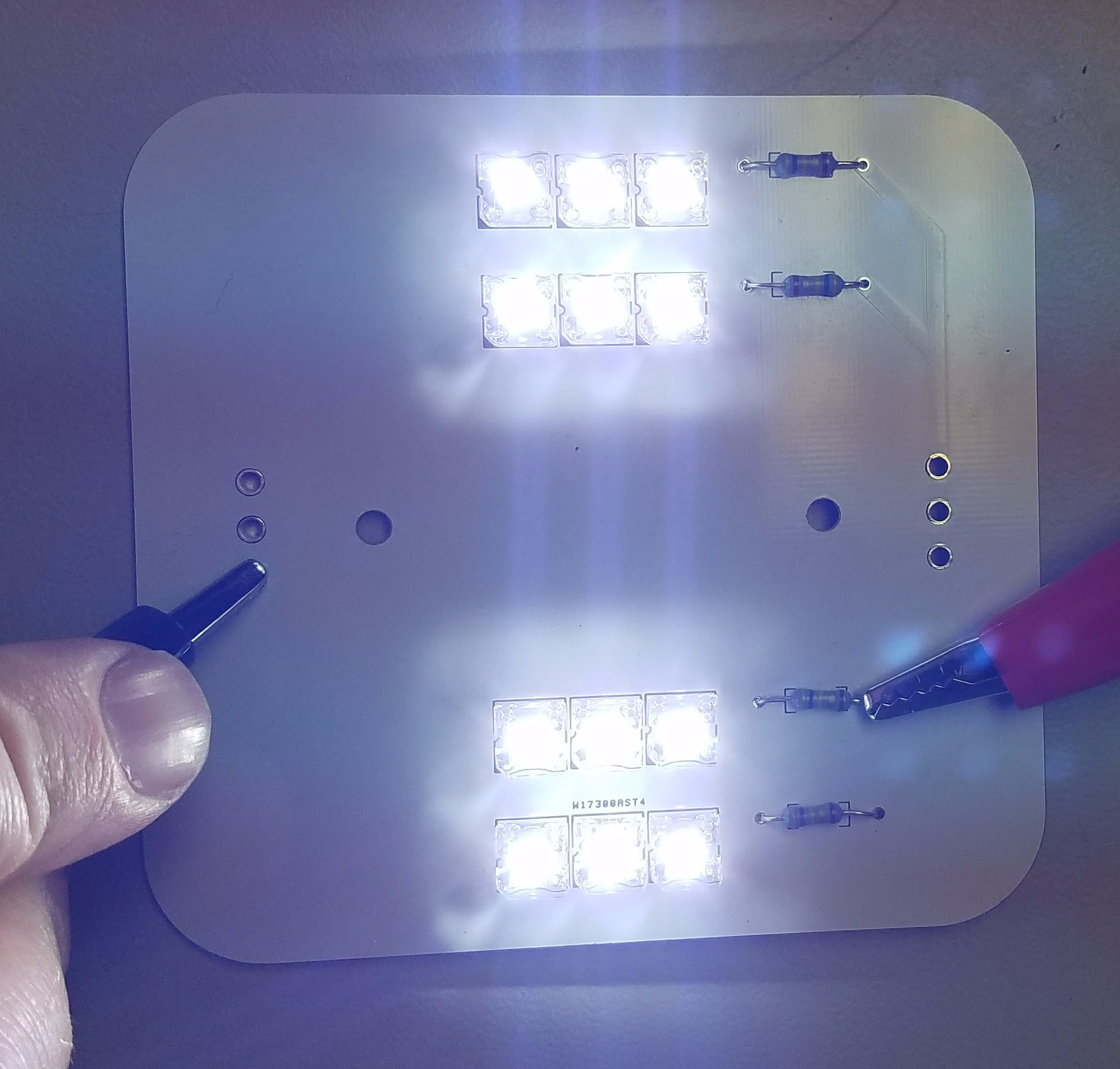
Testing the WHITE LED board section.
Now, the boards are complete and tested. They function great, and are now ready to final assembly. I will post again once I finish the wiring and mounting of the boards in the housings.
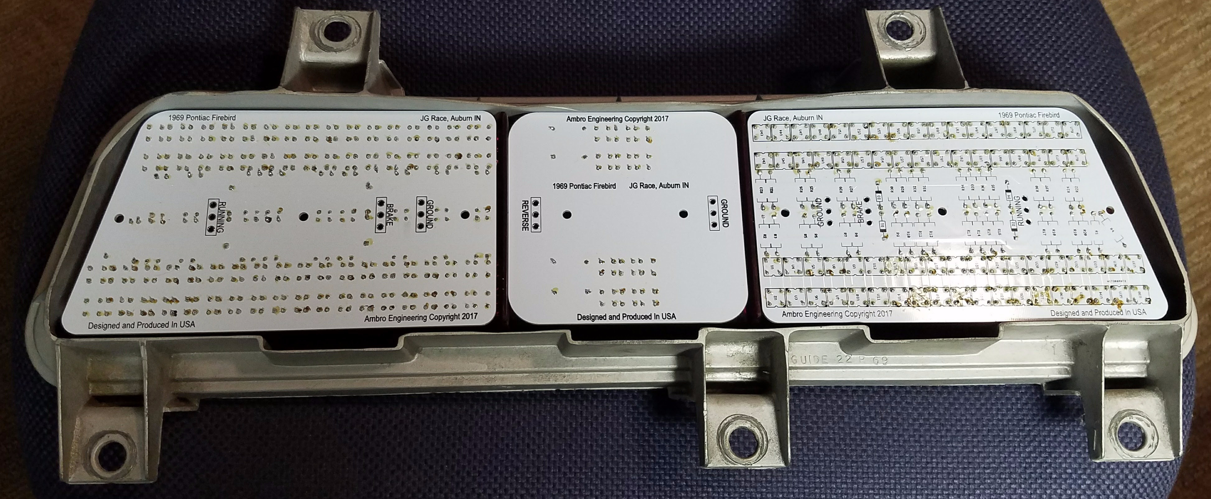
Test fitting the PCBs into the housings.
As promised, you can find all of the design files on my GIThub account here:
